


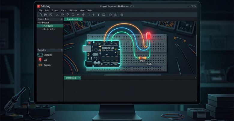
Fritzing is an incredible open-source initiative designed to support designers, artists, researchers, and hobbyists who want to take their hardware prototypes from physical layout to finished products. Whether you are building an Arduino-based automation system or sketching a quick concept, Fritzing bridges the gap between physical prototyping and professional documentation.
Here is a comprehensive breakdown of the Fritzing interface, its core tabs, and a step-by-step walkthrough to help you build your very first circuit.
Understanding the Fritzing Interface
Upon launching Fritzing, you will be greeted by a clean, multi-tab workspace that allows you to seamlessly transition between different stages of circuit design:
- Welcome: The default landing page where you can check the latest community news, tutorials, and project updates.
- Breadboard: This is where you will spend most of your time. It mimics a physical, experimental breadboard, allowing you to place components and feel as though you are wiring real hardware by hand.
- Schematic: An industry-standard tool for creating clean electronic schematics and circuit diagrams. Any component placed here automatically links to other tabs, though you will need to establish proper connections (routing) manually or using the Autoroute feature.
- PCB: This tool transforms your schematic and breadboard layout into a professional Printed Circuit Board (PCB) ready for manufacturing.
- Code: A built-in code editor that allows you to write, modify, and upload code directly to Arduino-compatible boards without needing an external IDE.
The Parts Library and Installing Custom Components
The right-hand side of the screen houses the Parts Bin, containing every component available for your design. You can easily find items using the search bar or category folders.
- Default vs. Custom Parts: While Fritzing comes with a rich standard library, you will often need specialized or custom modules. Pre-made Fritzing parts and community libraries can be downloaded from sources like GitHub.
- How to Install a New Part: Go to File -> Open, select your downloaded part file, and it will automatically appear in your Parts Bin under the “Mine” subcategory.
Step-by-Step Tutorial: Connecting a Croduino and an LED
To understand how Fritzing works in practice, let’s build a simple circuit featuring a Croduino (an advanced Arduino-compatible board) and an LED connected to pin D13.
Step 1: Placing the Core Components
- Open the Breadboard tab. The default breadboard on the screen will serve as your layout foundation. (You can delete unwanted default elements by right-clicking them and selecting Delete).
- Use the search bar in the Parts Bin to find your Croduino (or look for it in the Mine category if custom-imported) and drag it onto the workspace next to the breadboard.
- Search for an LED and a Resistor, then drag both onto the breadboard.
Step 2: Customizing Component Properties (Inspector Tab)
When you click on a component, the Inspector tab appears on the bottom right of the screen to let you modify its specifications:
- Click on the resistor. In the Properties section of the Inspector tab, change its resistance value from the default 220 Ω to 330 Ω.
- You can similarly modify other components, such as changing the color of the LED.
Step 3: Positioning and Understanding Pins
- If you hover your mouse over the right leg of the LED, a label reading “anode” will appear, indicating the positive terminal (+).
- You can click and drag any component pin or wire directly on the breadboard to reposition it.
Step 4: Wiring the Circuit
- Connecting the Cathode: The left leg (cathode) of the LED connects to one end of the resistor, and both need to be routed to the Ground (GND) pin on the Croduino. Click on a highlighted green connection point along that path, hold down the mouse button, and drag a wire straight to the GND pin.
- Changing Wire Color: Standard convention dictates that ground wires are black. Right-click anywhere on the new wire, navigate to Wire Color, and select black.
- Bending and Routing Wires: To make your layout clean instead of drawing straight diagonal lines, hold down Ctrl (on Windows/Linux) or Cmd (on macOS) while clicking and dragging the wire to curve and bend it neatly.
- Verifying Connections: To test if your components are properly wired, click and drag the Croduino or breadboard slightly—the attached wires should stay dynamically connected.
- Connecting the Anode: Complete the circuit by connecting the LED’s anode leg to digital pin D13 on the Croduino using the exact same drag-and-drop process, then style the wire with a vibrant color (like orange).
Step 5: Exporting Your Project
Once your circuit is fully assembled and verified, you can save or export your work by going to File -> Export and choosing your preferred image or document format.
#Fritzing #Electronics #Arduino #Croduino #PCBDesign #HardwarePrototyping #EmbeddedSystems #IoT